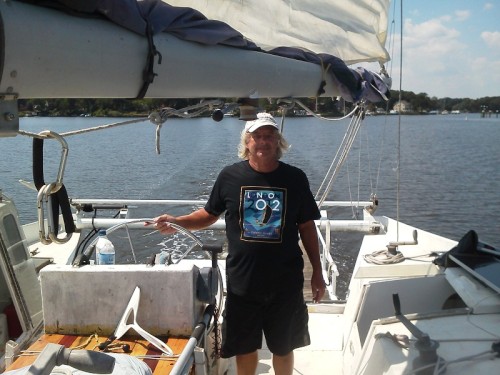
Kaimusailing
s/v Kaimu Wharram Catamaran
| Vessel Name: | Kaimu |
| Vessel Make/Model: | Wharram Custom |
| Hailing Port: | Norwalk, CT |
| Crew: | Andy and the Kaimu Crew |
| About: | Sailors in the Baltimore, Annapolis, DC area. |
17 April 2024 | St Marys, GA
Dinghy Skeg
I was suffering with what seemed like a cold and also had allergy symptoms. I awoke and felt fine. The green pollen that was coating everything was gone. Maybe it will return.
07 April 2024 | St. Marys, GA
Clammy Hands
Items came in from TEMU, the Chinese cut rate retailer. One was a nice little drone that cost about twelve and a half dollars. It looked like an easy thing to play with while I coughed and sneezed. I was fighting a summer cold, even though it is not summer elsewhere, it seems like it here. A nice [...]

02 April 2024 | St. Marys, GA
Sun Doggie
After laminating the cedar strips onto the gunwales of the dinghy I found the screws I used wouldn’t come out. The epoxy had seized them. The screw heads were stripped so I cut a straight slot in the heads with the cut off wheel. The cedar smoked when the screw heads got red hot. I could remove [...]
21 March 2024 | St. Marys, GA
Just Add Water
The rainy weekend started off with overcast and fog but no rain. It looked like I might be able to get something done on the D4 dinghy. I wanted to change the bow seat which is really the bow deck. The sailing option uses the deck to hold the freestanding mast. I didn’t like how the deck looked, [...]
01 March 2024 | St. Marys, GA
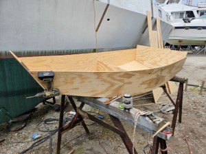
D4 Dinghy Alternative Seats
The rain event was more wind than rain, strong winds with gusts up to 44 mph. We drove into town to see what the harbor was like. There was a small sailboat that had dragged anchor and was sitting close to shore. The tide was out. We left and played with Bleu at Notter’s Pond.
23 February 2024 | St. Marys, GA
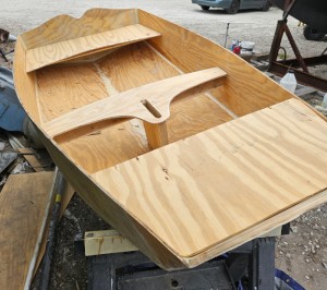
D4 Inside Seams
Day two of the dinghy build started out with me finishing wiring the hull bottoms together on the centerline of the bottom panels. This was much easier than the wiring of the chine edges of the bottom panels and the side panels.
BFB Proa Assembly
.
Back in the woodshop I continued with the outrigger canoe. I cut out the panels for the main hull sides. The hull sides consist of a total of 8 pieces of plywood, but they can be laid out with just 2 patterns. One pattern is the bow section, 5 feet long, and the other is the midship section, 4 feet long. A hull side consists of two bow sections at either end and two midship sections in the middle. The seams between the sections are butt seams with butt plates or butt blocks glued over the seams. The width of the plates is equal to the width of a scarf joint. The design puts these seams at stress points in the hull because they have a double thickness of ply. Where a scarf joint would provide equal strength as the surrounding plywood, the butt plates provide a double thickness of ply, thus greater strength.
.
The ama, or outrigger float, was wound up with its spanish windlasses, bulkheads, and center keel seam stitched with copper wire. The seam and bulkhead edges were then filleted with epoxy filled with 50/50 phenolic microballoons/"glue strong” mixture. Glue Strong is colloidal silica with 20 percent milled glass fibers. Instead of filleting the seams and then glass taping over them, the mixture I used provides plenty of strength and is lightweight and easy to work with.
.
After the epoxy set, the copper wires and spanish windlass twine were removed, and the tops of the bulkheads were trimmed down flush with the gunwales. I decided to install the flat deck on the ama with a 12“ circular cut out right amidships. It will just fit. In the cut out I’ll install a Gamma Lid, which is a screw on lid for a 5 gallon bucket available at the local home improvement store for less than 10 dollars. If the lid and its surrounding plastic rim won’t fit, I’ll cast the female threads into the deck opening out of epoxy mixture.
.
I cut out the two bulkheads for the main outrigger hull. They are rectangles 1 foot wide and reaching from the bottom of the boat up to the gunwale. They are installed 4 feet from the
bow(s) and form a flotation chamber with the deck at the bow. I made sure they were wide enough for the gamma bucket lid to form a hatch allowing access to the space in the bow. The shape of the side of the hull is slightly flared amidships, then going to vertical at the bow bulkheads, then with slight tumblehome at the bows. This produces the “destroyer bow” shape.
.
Amidships I plan to have no bulkhead, but will use a former to maintain hull shape while it is being built. Later, side decks will be installed to maintain the shape.
.
I would need an 18 feet long workbench to build the outrigger’s main hull, but my table is only 8 feet long. I made sawhorses along the lines of those in the “Kayak Shop” book. I made an extra one for the woodshop to use as a support when cutting long pieces of wood on the table saw.
.
The long stringers for the main hull were sanded smooth and then the hull sides were glued up, first each bow piece and midship piece were glued together producing 4 pieces that represented the bow and stern of each hull side, then these were glued together to produce the 2 pieces that are the hull sides. The stringers were glued on using sheet rock screws to clamp them together. This produced about 250 little holes left over after the screws were removed.
.
The hull sides were temporarily clamped together with the bulkheads clamped in place and then the ends of the stringers were trimmed. The gunwale stringers were lopped off and the ends rounded to a 1 1/4 inch radius. The chine stringers, called chine logs, were bevel cut so that they could fit inside the narrow angle of the bow.
.
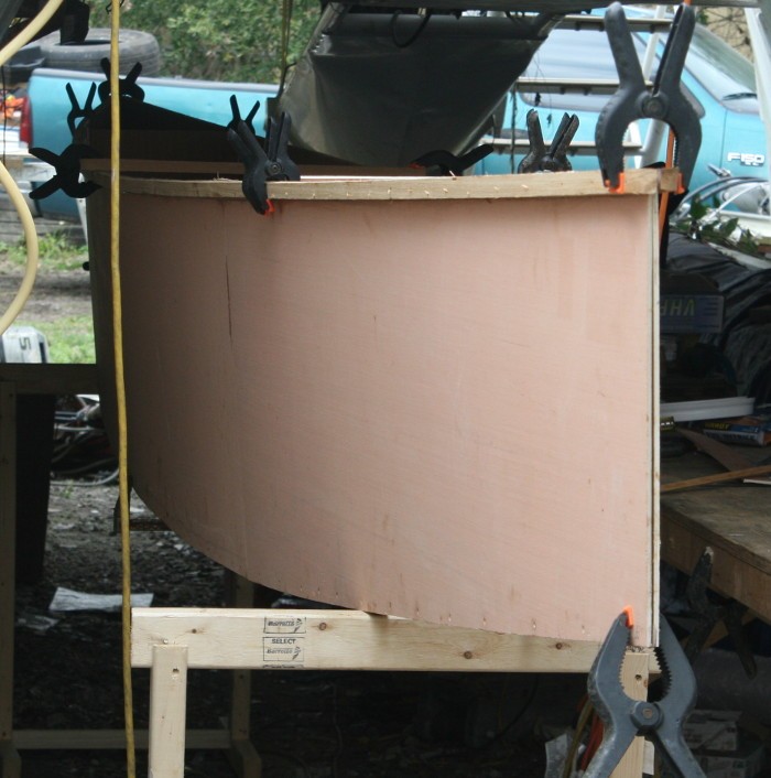
The midship beam was set by clamping a piece of stringer to one gunwale and adjusting the other till the beam was correct, 20 1/4 inches. The beam of the chines was set similarly to 15 inches. Now something looked wrong. The shape of the bottom, the shape made by the chine stringers, was distorted. It looked pinched, not fair, amidships. Then I remembered I made the bulkheads 12 inches wide to accommodate the Gamma Lid access ports. It was only a little change but it looked ugly. I experimented with the shape at the bulkheads, keeping the gunwale beam at 12 inches, but letting the chine beam reduce to around 10 inches, the original computer rendered beam. The gamma lid would still fit and now the hull looked fair again. The photo is of the hull being temporarily clamped, resting on the sawhorses.