
Aft Head, FlyBridge Wiring
Friday the 7th of May, 2010
I've done many things not documented in this continuing sage.
Aft head - while changing the discharge hose and intake hose to the aft head I encountered more hidden stuff. The old hose was impossible to pull out 20' of it. It had been run in a space underneath the starboard fuel tank. The hose had gotten partially squished and could not be removed except in sections. This is the discharge hose I'm speaking of. So, you can imagine what happened each cut to remove each section. Ran the new hose a different path of course. I had to remove the existing toilet and aft head decking to get the old hose out and new hose run. It smelled bad from 30 years of use. So, decided to change out the urine soaked plywood deck; cleaned and painted the hull underneath the deck area. Nice smelling now. I bypassed the through hull fittings and went straight to the holding tank. Now both head toilets are connected directly to the holding tank. And, now I have two UNUSED through hull fittings. Remove them and fill the hull back in, or, leave them with the seacocks in the off position, that's the question. The yard would like me to believe they need to be filled in. I don't know ABYC's stance on that issue. My thoughts they were ok to be there when needed. So,why would there be some urgency to remove them now they are no longer needed. And, who knows I might NEED them later. Salt water wash-down other, refrigeration A/C intake etc.? I'm leaving them and just and putting end caps on the fittings just in case the seacock leaks.
So, now just install the old toilet on the new deck and hook up the hoses. It just didn't sit right with me to use the old head either. So, I got a good deal on a new toilet like the one I had installed in the forward head. Now we have two nice new heads and good smelling decks.
NEXT PROJECT ISTHE WIRING MESS UNDER THE FLYBRIDGE. Yep lots of dangling wires under the flybridge. So, identify what's working and remove what's not. And, wire management of everything left. That's the plan.
Guess where they mounted the screw terminals for all connections up on the flybridge? Directly behind the hydraulic lines for the steering. So what happens where you put a screw driver between the hydraulic lines to screw something to the + terminals. Well if your screwdriver touches the hydraulic line, you short out the + supply to the grounded (- battery ) connection. I did not discover this by a bad accident, but rather checked my suspicions with my Volt Meter.. So, I wrapped my screw driver with electric tape to insulate it. A future project may be to relocate on install new terminal strips in a safer area under the flybridge.
Boat wiring is a curiosity at best. It seems 30 years ago about the only load for your hose batteries was lighting. And, the theory back then must have been a law of averages. It seems I have at least 200 amps of DC breakers that are cascade fed with #10 wire. #10 wire will safely conduct 30 amps of current. So, 200 amps would burn the wire. Yet that is how my DC breaker panel is wired from the battery switch. So as long as my DC load on all breakers does not exceed 30 amps, or 20 amps on anyone breaker everything will work and not catch fire. Maybe the Albin engineers added up the entire load and didn't see more than 30 amps at any time. And, boating breakers are often used as switches to cut circuits on and off. So, that many breakers are in the off position or are now supplying current. I would rather re-wire this panel so each breaker could carry it's full load. But that will be a winter project. I just keep track of my DC load and make sure I don't exceed that. Oh, yea,, what about the return path. - Negative, ground. I consistently find inadequate negative paths. Negative paths are NOT fused, switched or protected. So, nothing will trip a combined return path if it's overloaded. The entire negative buss at my breaker panel appears to be #8 wire. I will wire it with #2 at least when my winter wiring project starts up
Back to the flybridge. I don't have a wiring diagram of the flybridge. I figured two circuits from the DC panel below. There is also a + supply that I don't know how is run. But for now, I ripped out the old VHFs, depth finders and other dead stuff; fused all positive connections to the radio, GPS and depth sounder and attached the remaining wires in good supports. Nice and neat and labeled. Again the negative connections for everything seem to run back on a single #12 (20 amp) wire.
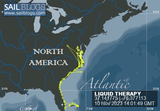
LIQUID THERAPY
Who: BROOKE & SUSAN SMITH
Port: DELTAVILLE, VA
- MAINTENANCE & OUCH
- Thursday, November 9, 2023 Day 24 Fall C...
- Tuesday, November 7, 2023 Day 22 Fall Cr...
- Monday, November 6, 2023 Day 21 Fall Cru...
- Day 19 Fall Cruise November 4, 2023
- Day 18 Fall Cruise November 3, 2023
- Day 16 Fall Cruise November 1,2023
- Day 15 Fall Cruise
- Fall Cruise Day 14
- Fall Cruise Day 10
Comments