Sailing in Abundance - Live Your Dream
The mark of a great shiphandler is never getting into situations that require great shiphandling. Admiral Ernest King, USN"
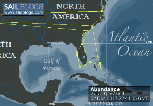
03 December 2017 | Tampa Bay Channel
02 December 2017 | Saint Petersburg, Florida
20 October 2017 | Salt Creek Boatyard and Marina
05 October 2016 | Maximo Marina
27 August 2016 | Maximo Moorings
24 August 2016
29 May 2016
28 May 2016
01 April 2016 | New Smyrna Beach, FL
16 March 2016 | Oasis Boat Yard
21 November 2015 | Oasis Boat Yard
28 September 2015 | Myrtle Beach Yacht Club in Little River, SC
14 June 2015
02 June 2015
16 May 2015 | Staniel Cay
02 May 2015 | Harbour Island, Eleuthera in the Bahamas
30 April 2015 | Harbour Island, Bahamas
17 April 2015
13 April 2015 | Bimini, Bahamas
06 April 2015 | Key West, FL
Abundance Gets a New Bow Thruster
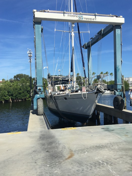
20 October 2017 | Salt Creek Boatyard and Marina
David - on the hard
When we are going into and out of tight places like marinas, the wind can move the bow (front) of the boat in ways that are dangerous - and can result in collisions with other boats or docks.
A device known as a bow thruster can mitigate this problem by adding a motor and propeller in the front that can be operated by the helmsperson.
We had one installed in 2014, an external model, but it proved inadequate for our 52,000 pound boat with a high freeboard (wind side area).
So we decided to haul her out once again an install a proper internal thruster, this time a 10 horsepower Vetus model BOW16024D, that runs on 24 volts and has 350 pounds of thrust.

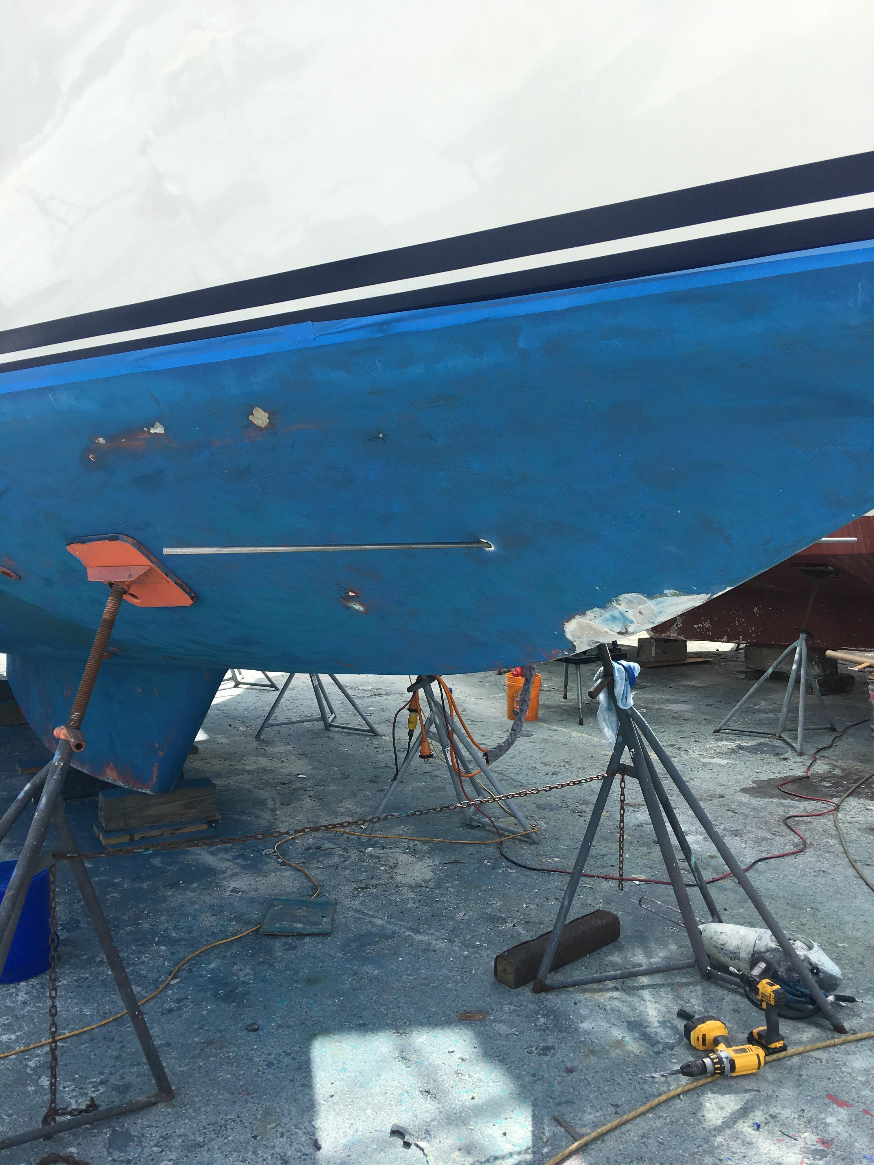
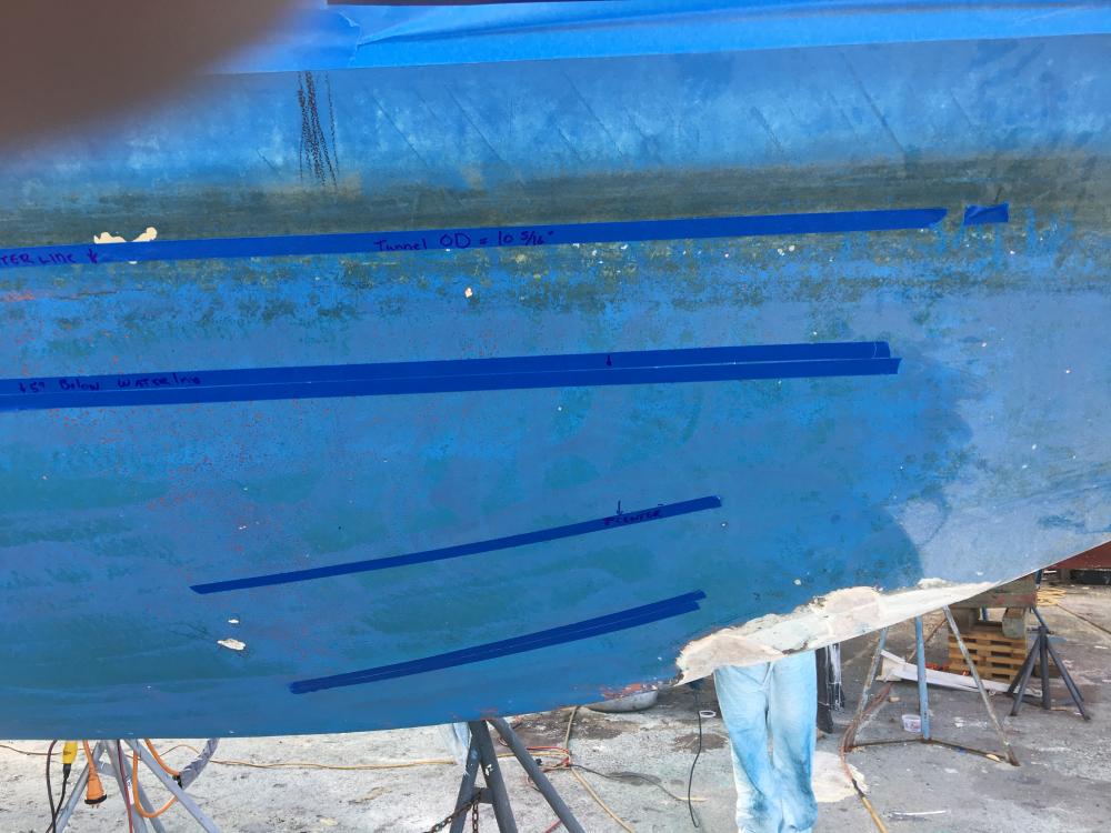
In the above photo, I have laid out some boundaries. The Vetus thruster requires only 1/2 of the tunnel diameter below the waterline. The upper tape defines the waterline and the next one down is the 1/2, or 5" line since the tunnel is 10" in diameter.
The lower rows of tape are the lowest the tunnels can be in the hull. I chose 5" as the minimum distance between the bottom of the tube and the bottom of the hull.
My goal was to keep the thruster as far forward as possible for two reasons. The first, the minimize the impact on cabinetry in the V berth and second, the provide a longer moment arm for the thruster to operate with and create more turning force.
Below the tape area is an area with the blue bottom paint removed. This is the area where the old external thruster was attached. I had to repair the old 2" hole and 2 bolt holes in the hull.
In the photo above, you can see I've decided on a center for the tunnel and inserted a 1/2" steel rod through a hole in each side. This is a guide rod for the router appliance that I used to cut the holes for the tunnel.
You can see the old external thruster laying on the ground near the yellow drill. Way too small for Abundance. It did work in very light wind, but it slowed the boat about 1/2 of a knot.
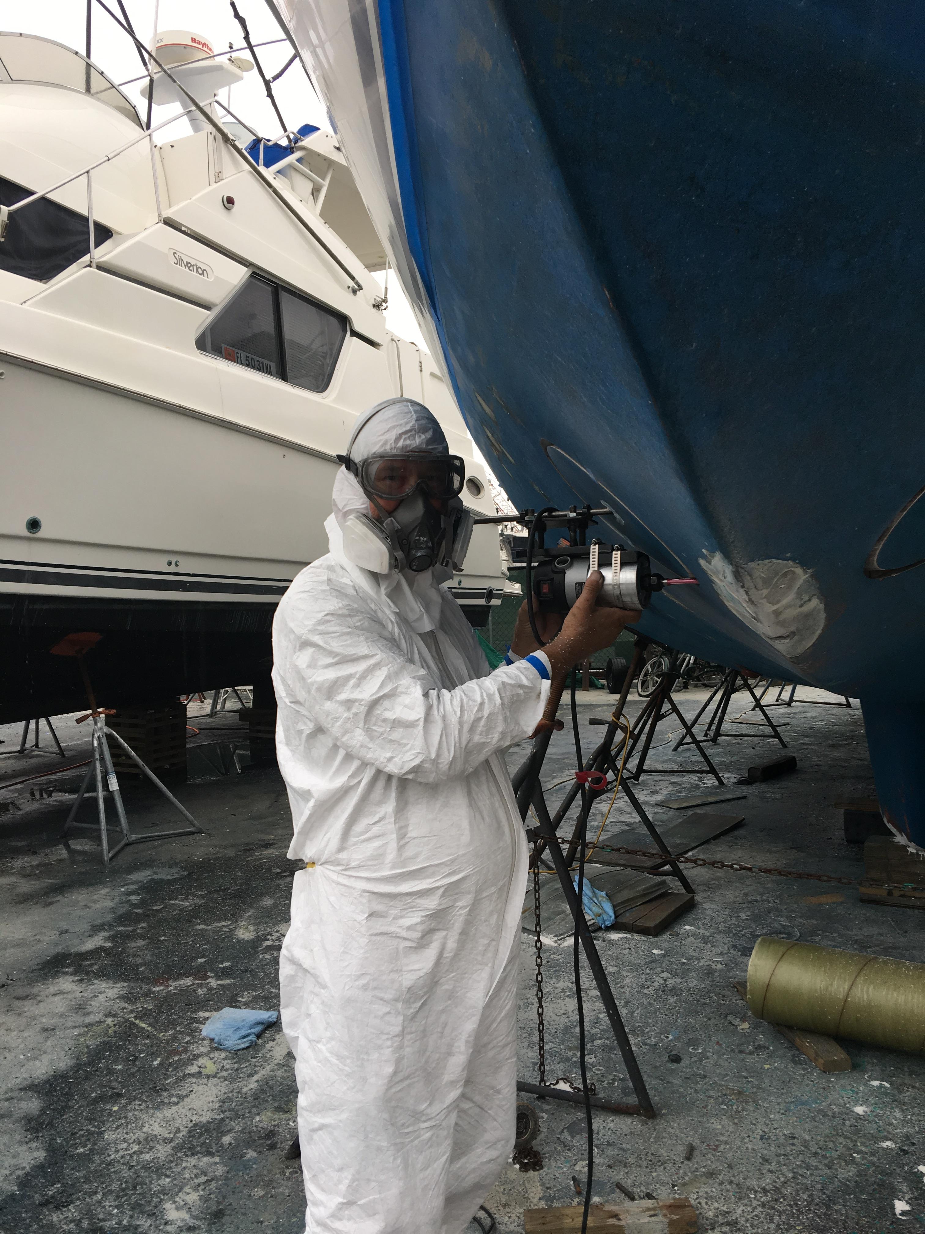
Here I am suited up for cutting the holes. Bill Drewes, a coworker at Farmer Mold and Machine Works, created and made the router appliance that keeps a constant radius on the cutting bit while the router is rotated around the guide rod.
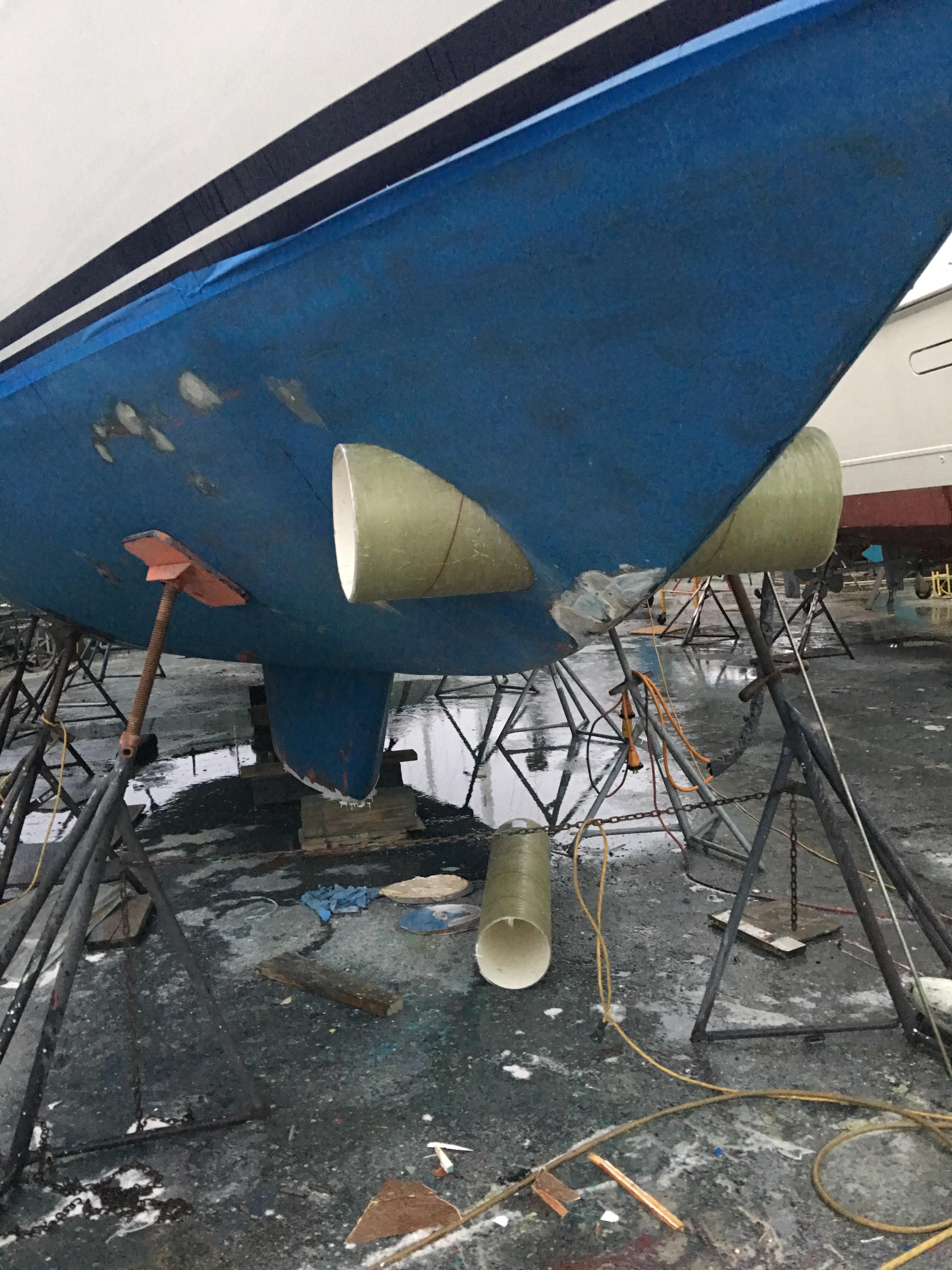
After the holes were cut, I inserted the tube for a fit check. No more than a 1/8" gap occurred around the periphery of each hole. Well done, Bill! Thank you for making the great router appliance.
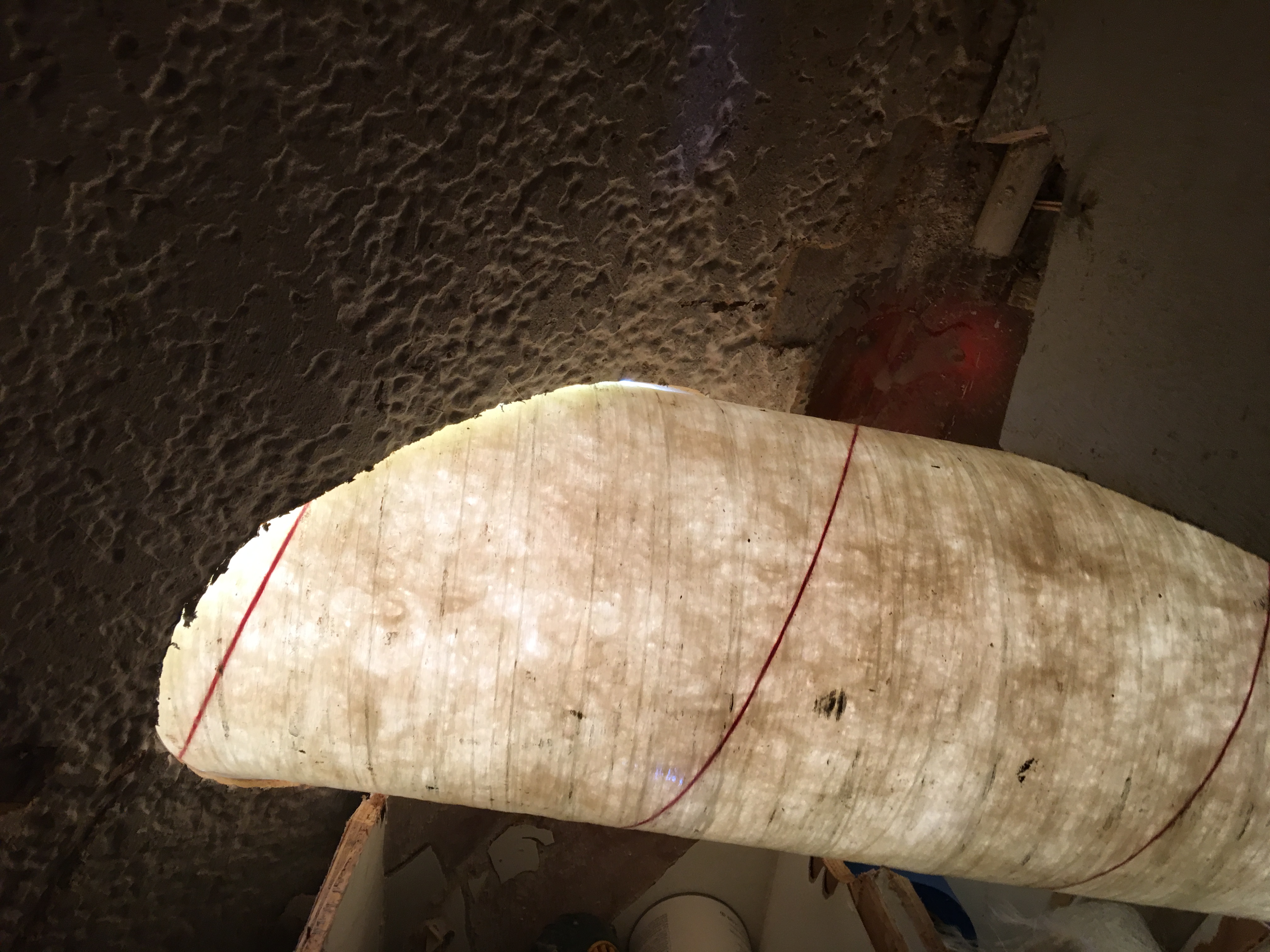
You can see the close fit in the inside where sunlight illuminated the tube.
This is a view of the glassed-in tube in the V berth. I used West Systems epoxy and bi-axial glass. Don't ever used chopped strand matte with epoxy. It won't dissolve the binder and the matte will not lay down. I applied 2 layers of matte then 4 layers of bi-axial with increasing length of strips.
This was after we packed thickened epoxy into the joints all around the tube.
I glassed the outside edge and faired it. I also added "eyebrows" ahead of the tube, with a 1" gradual rise to decrease the amount of water that crashed into the aft portion of the tube when underway. I also radiused the joint where the tube and hull meet.
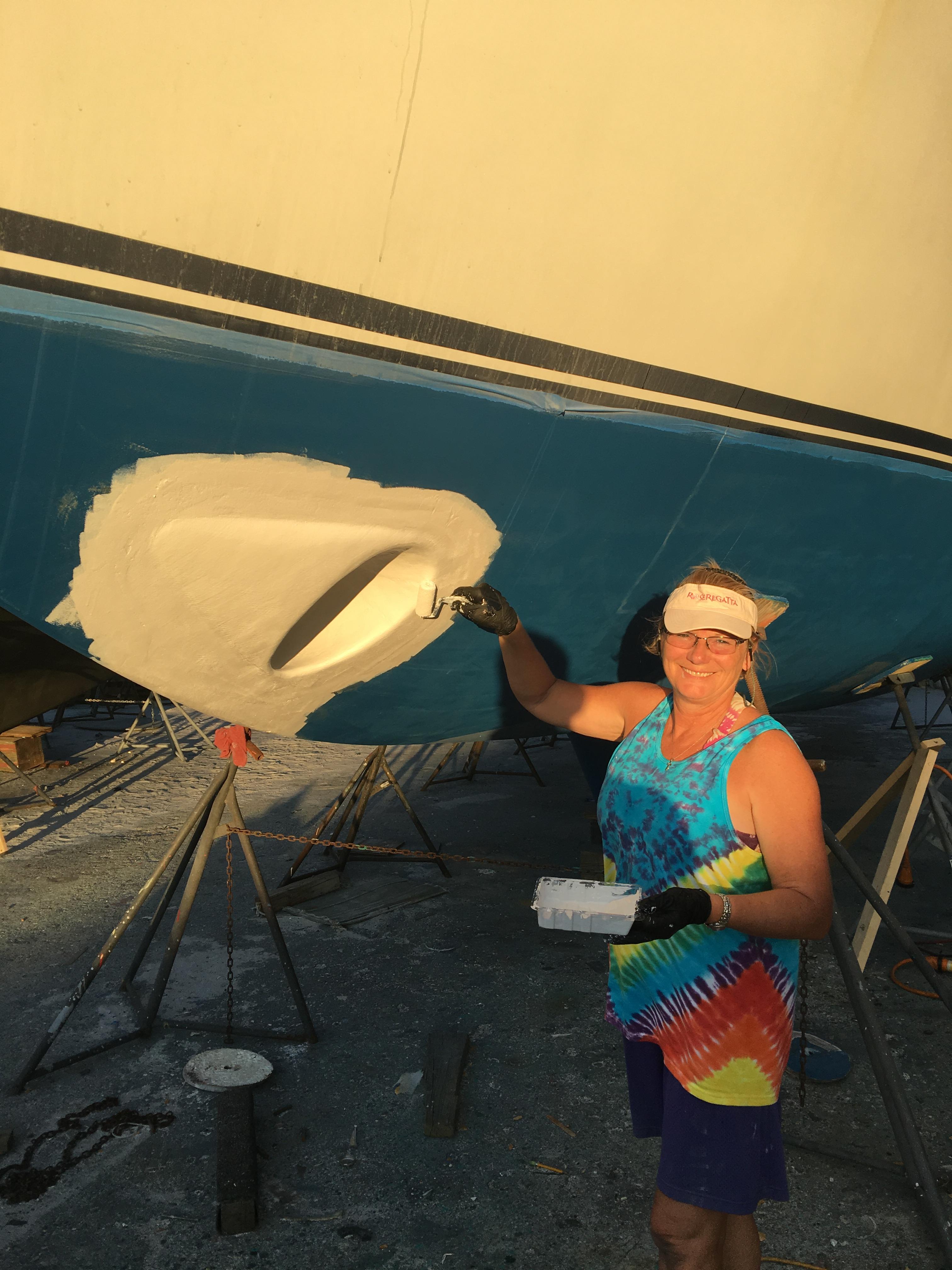
Yvonne is applying the barrier coat, Interlux Interprotect 2000 before applying the anti-fouling layers.
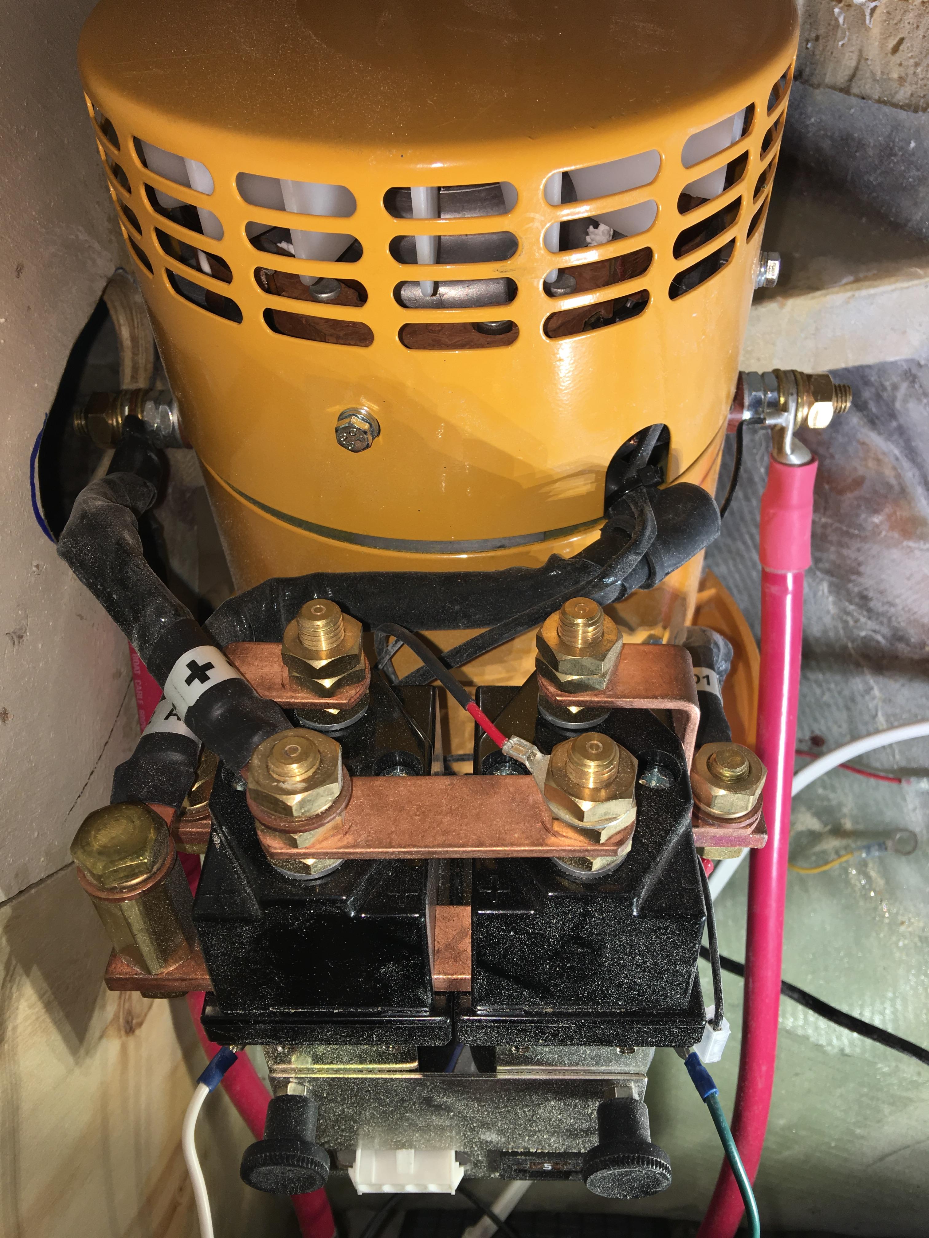
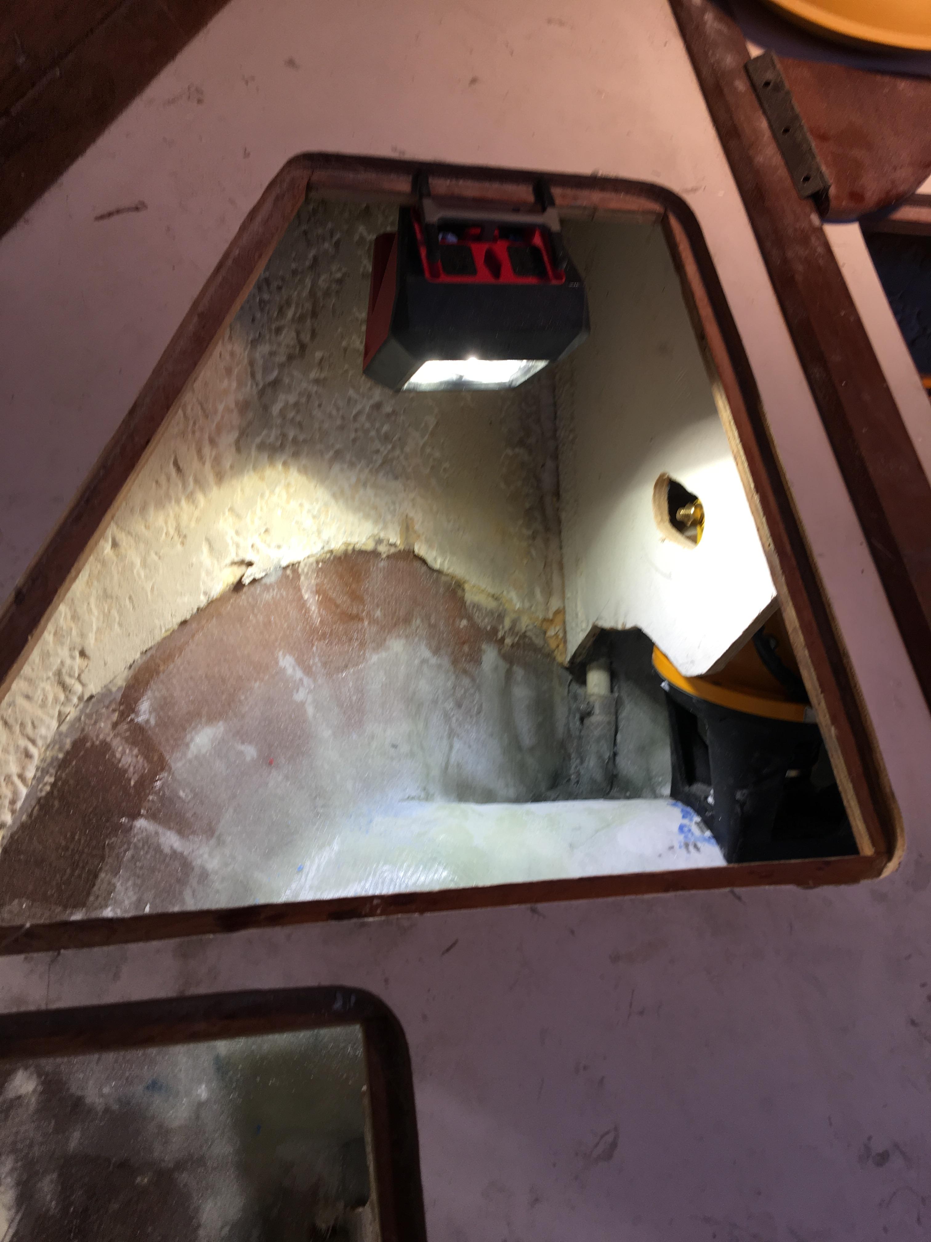
This is what the motor looks like in the V berth.
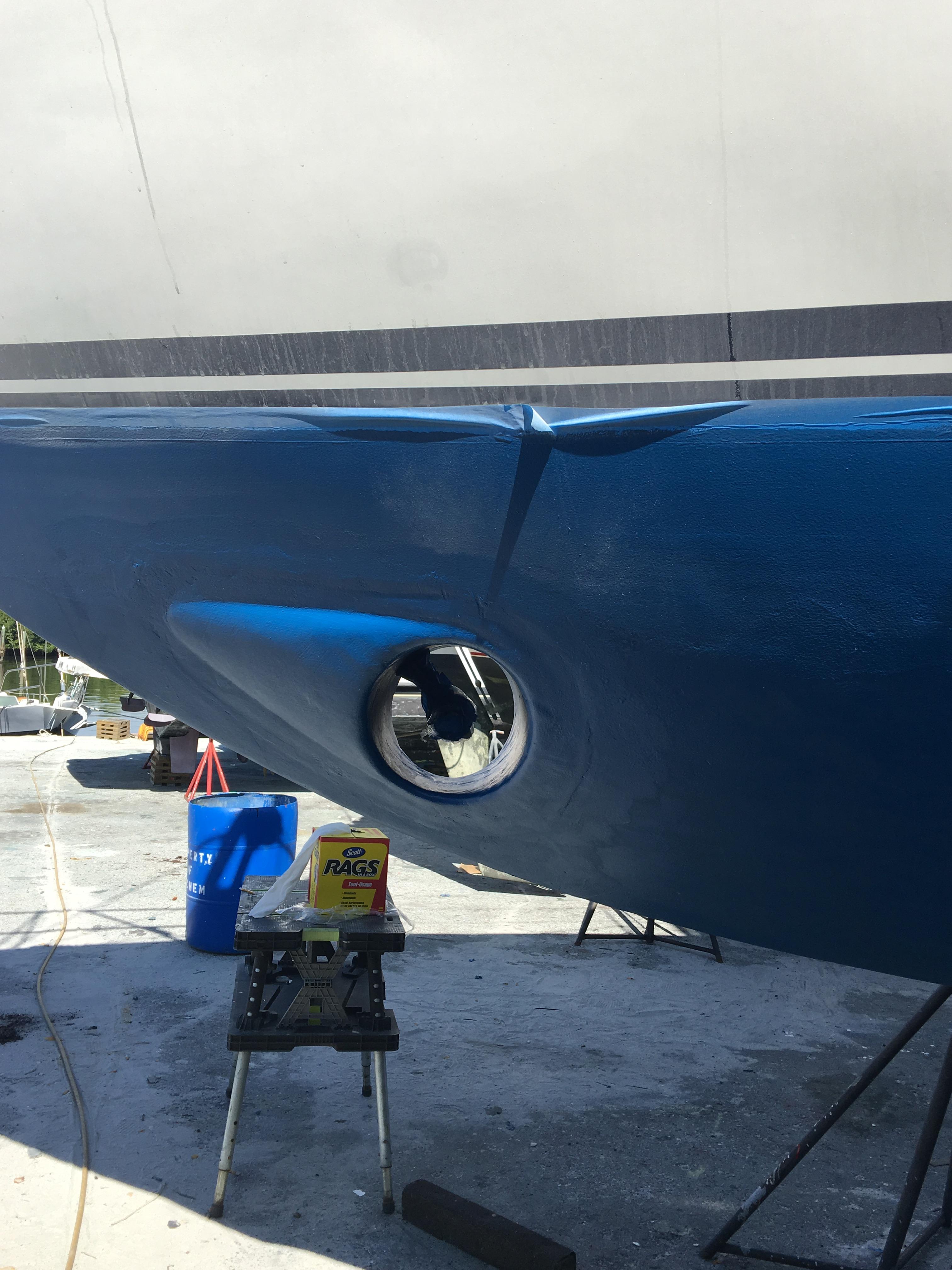
This is the appearance after bottom paint was applied. I put the propeller on later. It tested okay the first time and has a lot of thrust!
A device known as a bow thruster can mitigate this problem by adding a motor and propeller in the front that can be operated by the helmsperson.
We had one installed in 2014, an external model, but it proved inadequate for our 52,000 pound boat with a high freeboard (wind side area).
So we decided to haul her out once again an install a proper internal thruster, this time a 10 horsepower Vetus model BOW16024D, that runs on 24 volts and has 350 pounds of thrust.
In the above photo, I have laid out some boundaries. The Vetus thruster requires only 1/2 of the tunnel diameter below the waterline. The upper tape defines the waterline and the next one down is the 1/2, or 5" line since the tunnel is 10" in diameter.
The lower rows of tape are the lowest the tunnels can be in the hull. I chose 5" as the minimum distance between the bottom of the tube and the bottom of the hull.
My goal was to keep the thruster as far forward as possible for two reasons. The first, the minimize the impact on cabinetry in the V berth and second, the provide a longer moment arm for the thruster to operate with and create more turning force.
Below the tape area is an area with the blue bottom paint removed. This is the area where the old external thruster was attached. I had to repair the old 2" hole and 2 bolt holes in the hull.
In the photo above, you can see I've decided on a center for the tunnel and inserted a 1/2" steel rod through a hole in each side. This is a guide rod for the router appliance that I used to cut the holes for the tunnel.
You can see the old external thruster laying on the ground near the yellow drill. Way too small for Abundance. It did work in very light wind, but it slowed the boat about 1/2 of a knot.
Here I am suited up for cutting the holes. Bill Drewes, a coworker at Farmer Mold and Machine Works, created and made the router appliance that keeps a constant radius on the cutting bit while the router is rotated around the guide rod.
After the holes were cut, I inserted the tube for a fit check. No more than a 1/8" gap occurred around the periphery of each hole. Well done, Bill! Thank you for making the great router appliance.
You can see the close fit in the inside where sunlight illuminated the tube.
This is a view of the glassed-in tube in the V berth. I used West Systems epoxy and bi-axial glass. Don't ever used chopped strand matte with epoxy. It won't dissolve the binder and the matte will not lay down. I applied 2 layers of matte then 4 layers of bi-axial with increasing length of strips.
This was after we packed thickened epoxy into the joints all around the tube.
I glassed the outside edge and faired it. I also added "eyebrows" ahead of the tube, with a 1" gradual rise to decrease the amount of water that crashed into the aft portion of the tube when underway. I also radiused the joint where the tube and hull meet.
Yvonne is applying the barrier coat, Interlux Interprotect 2000 before applying the anti-fouling layers.
This is what the motor looks like in the V berth.
This is the appearance after bottom paint was applied. I put the propeller on later. It tested okay the first time and has a lot of thrust!
Comments
| Vessel Name: | Abundance |
| Vessel Make/Model: | 50' Custom Center Cockpit Cutter |
| Hailing Port: | Las Vegas, NV |
| Crew: | David and Yvonne Hoch |
| About: | David retired from Clark County on 11/11/11 and Yvonne is an Occupational Therapist who will be working as a travelling OT over the next few years to help keep the cruising kitty pumped up. |
| Extra: | We have been doing improvements to Abundance to make her more comfortable and safe for worldwide voyaging. We will leave Saint Petersburg, FL on March 4, 2016 headed for the South Pacific |
Abundance's Photos - Main
 |
 |
We hauled the boat on October 20th, 2017 to install a thruster. We were on the hard for three weeks and installed a Vetus BOW16024D. Very nice!
23 Photos
Created 14 November 2017
|
|
Local activities in St. Pete and elsewhere while working on the boat and working full-time jobs
30 Photos
Created 16 May 2017
|
|
Arrived April and left in March of 2017
61 Photos
Created 5 October 2016
|
|
Left Saint Augustine 3/19/16 for Saint Petersburg
7 Photos
Created 1 April 2016
|
|
On the Hard at Oasis Boat Yard from Thanksgiving 2015 to Easter 2016 - Bottom Job, topsides paint and more
2 Photos
Created 1 April 2016
|
|
 |
 |
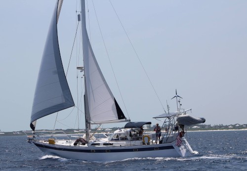
Abundance begins her cruising life with eager crew, David and Yvonne. We left St. Petersburg, FL on April 4, 2015 and went to Longboat Key to celebrate Easter and our starting the journey on Monday, April 6th.
47 Photos
Created 29 April 2015
|
 |
Victor and Robin joined us for a week of marina-hopping along the west coast of Florida
40 Photos
Created 18 June 2013
|
 |
We hauled the boat for many improvements including a bottom job, bow thruster, keel coolers, fish finder, rudder repair and pressure wash decks.
69 Photos
Created 18 June 2013
|
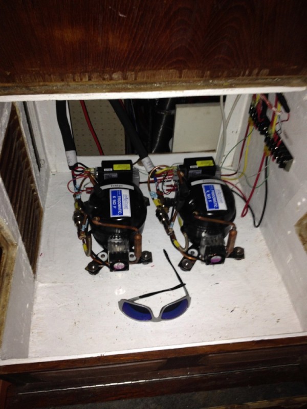 |
We removed the Grunert AC450 holdover plate system and installed two Danfoss compressor-based systems with evaporator plates.
7 Photos
Created 18 June 2013
|
 |
We covered the existing cabin sole with NuTeak, a two-month project
20 Photos
Created 18 June 2013
|
 |
 |
44 Hour Passage with some great sailing
19 Photos
Created 23 December 2011
|
 |
First port of call - Gardner's Marina then Golden Nugget
15 Photos
Created 23 December 2011
|
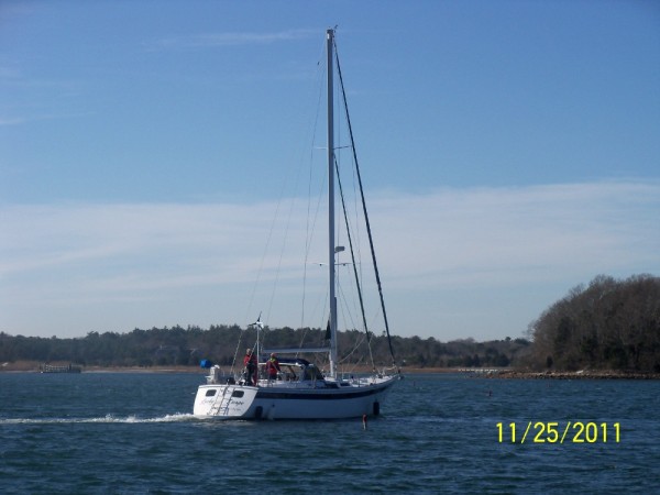 |
Sailing (motoring) to Atlantic City, November 25th, 2011
13 Photos
Created 23 December 2011
|
 |
Photos taken by the Surveyor, Jeff Gonsalves
40 Photos
Created 23 December 2011
|
 |
Who: David and Yvonne Hoch
Port: Las Vegas, NV