Kaimusailing
s/v Kaimu Wharram Catamaran
| Vessel Name: | Kaimu |
| Vessel Make/Model: | Wharram Custom |
| Hailing Port: | Norwalk, CT |
| Crew: | Andy and the Kaimu Crew |
| About: | Sailors in the Baltimore, Annapolis, DC area. |
17 April 2024 | St Marys, GA
Dinghy Skeg
I was suffering with what seemed like a cold and also had allergy symptoms. I awoke and felt fine. The green pollen that was coating everything was gone. Maybe it will return.

07 April 2024 | St. Marys, GA
Clammy Hands
Items came in from TEMU, the Chinese cut rate retailer. One was a nice little drone that cost about twelve and a half dollars. It looked like an easy thing to play with while I coughed and sneezed. I was fighting a summer cold, even though it is not summer elsewhere, it seems like it here. A nice [...]

02 April 2024 | St. Marys, GA
Sun Doggie
After laminating the cedar strips onto the gunwales of the dinghy I found the screws I used wouldn’t come out. The epoxy had seized them. The screw heads were stripped so I cut a straight slot in the heads with the cut off wheel. The cedar smoked when the screw heads got red hot. I could remove [...]
21 March 2024 | St. Marys, GA
Just Add Water
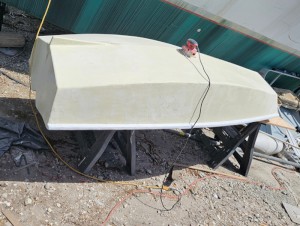
The rainy weekend started off with overcast and fog but no rain. It looked like I might be able to get something done on the D4 dinghy. I wanted to change the bow seat which is really the bow deck. The sailing option uses the deck to hold the freestanding mast. I didn’t like how the deck looked, [...]
01 March 2024 | St. Marys, GA
D4 Dinghy Alternative Seats
The rain event was more wind than rain, strong winds with gusts up to 44 mph. We drove into town to see what the harbor was like. There was a small sailboat that had dragged anchor and was sitting close to shore. The tide was out. We left and played with Bleu at Notter’s Pond.
23 February 2024 | St. Marys, GA
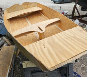
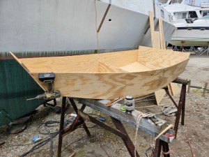
D4 Inside Seams
Day two of the dinghy build started out with me finishing wiring the hull bottoms together on the centerline of the bottom panels. This was much easier than the wiring of the chine edges of the bottom panels and the side panels.
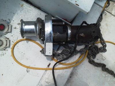
Sprint 1000 Windlass Repair
.
Right now, the older Toughbook, CF-50, is running fine with Navigatrix and the package of US BSB charts is loaded along with the whole world vector set in CM93. Next it was tested on board the GPS antenna and worked fine..
.
The topping lift for the main boom was finished by adding a 4:1 block and tackle between the boom and the lower end of the line installed at the top of the mast. The decks were cleared of the dyneema topping lift line that didn't work out.
.
Kaptain Kris had finished an adapter for the Sailomat self steerer after about 7 months of procrastination. This adapter attaches the servo oar to the servo oar shaft. It is made out of a piece of heavy stainless pipe, 1/4" wall thickness, that was slit lengthwise with a slot for a servo oar which was 3/4" thick. The lower end of the slot has a crosshole for a pivot pin. The servo oar trails back at an angle which provides negative feedback to the self steering system. The more it rakes back, the harder it is for it to swing out to the side. As it swings out, the water pressure tries to force it back to center. I thought it would be a good idea to enable a variable angle so I could adjust how much the oar trailed back. This is done by securing the top of the oar to the stainless pipe with a bolt from the rear, through the pipe wall, and into the oar. The oar wants to trail backwards on its pivot and the bolt at the top restrains it. Adjusting the bolt in and out angles the oar from parallel or inline with the oar shaft, or trailing at an angle.
.
An air blade also has to be made. The description in the user manual for the Sailomat says the counterweight of the air blade is to be adjusted so that the blade tends to stand up vertical. From the illustration measurements were made and the air blade scales to about 45 inches tall with the head ending in a 10 inch round and angling down to the foot about 5 inches wide. The midpoint is about 2 feet above the pivot, so a 2 foot lever and weights were used to balance against the counterweight from its minimum to maximum. It comes out that 1 lb 3/4 oz balances at the minumum and twice that at the maximum. Working out the weight of a plywood air blade, a 1/4" thick blade would balance right at the middle of the counterweight's range.
.
Because we had finally got a little rain, the main fuel tank was drained using the new petcock and a small quantity of fuel with water in it came out. It was only a few ounces. We need a bigger rain storm now to see if more water gets into the tank.
.
The bronze replacement for the failed main halyard winch came in and it looks good. It is an older Lewmar that uses slightly smaller winch "teeth" than what is universally used these days. The universal star pattern is derived from an 11/16 inch square drive, the old style is 5/8, so a little filing will make a new style winch handle fit an old style winch. There are old style winch handles that come up from time to time on eBay, so I am watching one for purchase.
.
The winch was mounted in the mean time and I took a trip up the mast to investigate one of the eye bolts of the main halyard at the top of the mast. I noticed it was loose the last time I was up there and had to make sure it wasn't going to fail. If it did, the main halyard would be out of commission. When I looked at it, it was very loose, so its lock nut was tightened.
.
The deck table was opened up to allow access to the fuel tank and the rope locker forward of it. I was looking for the source for rain water to get into the fuel tank. The rope locker is home of the reluctant anchor windlass which was now getting attention. Voltage checks at the contactor that switches high amperage 12 VDC to the windlass showed that the voltage was there and pressing the foot switches, at least the UP switch, put 12 V to the windlass. It wasn't turning and acted like a dead short. This could mean an electrical short in the windlass or a stalled motor.
.
When I unbolted the windlass and opened it up, the gear box had rust and water in it. The motor was frozen, but the brushes and commutator inside were clean just as if I burninshed them yesterday. It wouldn't come apart without some prying and banging with a hammer. It looks like some of the permanent magnets inside had come loose and bonded to the armature which had some rust on it.
.
There are many postings on the internet about problems with this model windlass. It has one big basic design flaw, the windlass, gearbox, and motor are all inline vertical, water can get into the windlass and then into the gearbox. Soon water migrates from the gearbox down into the motor. The bottom of the whole unit is the brush assembly for the motor, so any water that makes its way down ends up in an aluminum cup with electrical wiring, a bearing, motor brushes, and a copper commutator that will corrode instantly in salt water. The original assembly had a rubber sleeve to shield the motor from water in the rope locker, but instead it prevents water from escaping from the motor.
.
We had rebuilt this windlass three times and used it but two. Not joking. It works for a while then packs up. Of course the motor is awful to work on. Replacement? Not available. And for good reason. Anyone who had this windlass would have bought a replacement, depleting the market. The fact that the manufacturer went belly up and most customers moved on to better units meant that there was a shrinking market for parts, so now there aren't any.
.
Can we make it work again? Why bother? A replacement 1000 or 1500 watt windlass runs from about a thousand to two thousand dollars. A new windlass will require a new installation which makes the old mounting hole a problem. It would be worth our while to see if we can make it work again.
.
The loose magnets were removed and the interior of the motor was scraped clean of old magnet glue and rust. An 80 grit dremel flap disc was used to further clean up the interior surface. Some of the magnets were shattered. Cleaning with acetone and alcohol made the surfaces good for gluing. This is a 4 pole motor made by Facmo and it might be possible to get a replacement. The magnets are positioned in 4 linear rows of two each, so there are 8 individual magnets. Only one row remained in place. The magnets are either north pole facing in toward the armature or south pole facing in. Careful measurements were made and the motor cylinder was marked for accurate magnet position. Thin wood stirring sticks were clamped to the cylinder to provide a guide for holding the magnets in correct position. The unshattered magnets were glued in place with 5 minute epoxy and held in place with small clamps. The magnets will stick to the cylinder on their own, but because they repel each other, when two are positioned in line they will tend to separate from each other. They also try to slide over, attracted by their neighbors of opposite polarity. Shattered magnets were glued in place one piece at a time, care being taken to make sure there were no high spots, because the armature has only a fraction of an inch clearance from the magnets.
.
The failure of the motor is probably due to moisture causing rusting of the inside of the cylinder. Rust takes up more room than unrusty steel, so the magnets mounted inside the cylinder would be squeezed toward the armature which eventually would contact them. This would seize the motor. Also the rusty cylinder surface would no longer hold the magnets in place, so they would become loose.
.
After all the magnets were positioned with the 5 minute epoxy, the inside of the cylinder was painted with regular epoxy which would further bond the magnets by migrating under them via capillary action. Finally colloidal silica putty was smooshed between the magnets carefully to create fillets that would keep the magnets from any tendency to slide sideways and also keep them from collapsing inward toward the armature.
.
The armature was sanded to remove rust from the steel core and cleaned with solvents to remove any moisture and rust dust. The end bearing in the brush assembly was repacked with grease with care being taken to keep grease from getting on the armature commutator or the brush holders. The motor was put back together and ran perfectly.
.
The windlass was reassembled and remounted. There was still the problem that the control system was only clicking the contactor in one direction. It turned out that the UP function of the contactor worked, but the DOWN contact was not being made. The switches were checked and they worked normally. I would have to replace the contactor.
.
The picture is of the windlass unmounted and laying on its side. You can see its linear construction, everything inline vertically.